Note:

Should you wish to follow the G11 'do it yourself' project from the very beginning, then please start reading the oldest posts first. They are located in the Blog Archive.

Friday, July 31, 2015

Loading the .hex boot file into G11 micro controller

Bootloading is a fairly straight forward procedure.
No programming knowledge is required - as long as you follow the instructions outlined in this chapter.

To get the job done, you need the following:

1. PICKit2 or a similar programmer suitable for 18F4550 Microchip micro controller
2. a cable to connect PICKit2 and G11 board
3. the hex file

PICKit2 [or PICKit3 as well as number of clones] is available on eBay for around $20-$30 postage included. My preference is old and reliable PICKit2 but this unit is no longer in production so it is a bit hard to find. Again, any unit will do the job as long as it is suitable for G11 uc which is 18F4550.

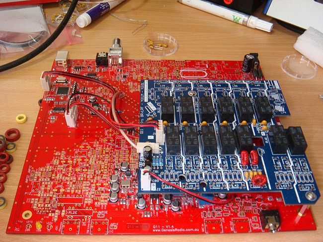
The connecting cable is something you need to make yourself. One end of the cable will have a 7 pin header to match J5U on G11 board. On the other end it will have a 5 pin header to match the PICKit output connector. Only 5 pins will be interconnected so you need a length of 5 wire ribbon cable. Keep it reasonably short.

Wire as per photo. The white triangle on the PicKit is alignmnt mark for pin 1. Pin 6 is not connected.

Wiring order on the J5U side:

Pin 1 on the top is not connected, pins 2 and 3 are joined together, and the others are as per the photo.

The hex file itself was mailed to you at the time you've placed an order for G11 bare board. You may have overlooked that, so go and check your inbox. If you haven't got it, or can't find it, email me again with your callsign and paypal receipt.

Assuming that you have previously installed PICkit on your PC, you are now ready to go!

1. make sure that the G11 board is not connected to power.
2. connect the PICKit and G11 with the cable you've just made, then connect the programmer via USB cable to your PC.

3. run it!

4. if your uc is installed correctly, it will be recognized by programmer with 'device' showing PIC18F4550.

5. enable VDD by ticking the box next to ON. The 5.0V should be pre-set automatically.

6. try the connection by clicking on Blank Check. If the connection is working fine, you will see the message 'Device is Blank'.

If device is not blank, click on Erase then Blank Check again.

7. Go to "file" then "Import HEX file". Locate G11boot.hex, then Open.

8. Programmer screen will display "Hex file successfully imported" and you can see part of the code.

9. Click "Write". After few seconds you will see "Programming Successful" message.

10. The USB led on G11 board will be lit.

At this point you have successfully loaded G11 boot file.

NOTE: clicking on 'Verify' will result in error message. The verification process is not possible due to code lock. Ignore this warning.

You are now ready to proceed to the next phase of assembly: installation of USB components.

NOTE: if you are using other programmer than PICKit 2 or PICKit 3, here is the schematic diagram which explains how to connect the programmer.

Link to diagram.

Thursday, July 23, 2015

Getting started: microcontroller unit

The fun starts with the assembly of the microcontroller unit, schematic diagram page 12.

The build itself is straight forward, all the designators are clearly marked on PCB and there is plenty of room to maneuver around.

Install U1U and components around it, as well as J5U, diodes and resistor as shown above.

NOTE: make sure to install ferite bead FB1U (not shown on the picture above)

Your uC is now ready for boot load.

If you really want to install just the essential components to get the uC ready for loading boot file then install only uC, crystal, C18 and C19, D1, D2, C20 and C10, Resistors R3U and R1U, connector J5U, LED diode LD2U and FB1U ferrite bead. You are now ready to move to next phase.

Wednesday, July 22, 2015

G11 Schematic diagram and PCB layout

It goes without saying: the best time to check out schematic diagram is BEFORE you start parting with your hard earned cash and investing in components.

G11 schematic is very much straight forward affair.

Download it form here: G11 schematic diagram, pdf file.

The next step is to get familiar with the PCB layout. Here it is: PCB layout, pdf

The printed circuit board is double sided, red soldermask, gold plated, 220x200mm. You'll love it - easy to solder, and most importantly you will be proud of your workmanship.

Have fun!

Monday, July 20, 2015

G11 Gallery: Classic, multiband and monoband QRP transceivers

For your enjoyment: photos of a few GenesisRadio G11 units, assembled, ready to go on air!

M0HDF G11 classic 5 band unit

ZL2PO G11 multiband

SP9DLM

JA1 ?? G11 multiband

N2BHA G11 classic 5 band unit, soon to be converted to multiband unit

WZ3HMT G11 classic 5 band unit

WB0QOA, DavidG11 multiband.

VK2DX G11 classic 5 band unit 30/20/15/12/10m. 84 DXCC worked.

Attention G11 owners: to have your G11 featured please email 600 px wide photo to nick[at]clockmaker.com.au

Thank you!

Sunday, July 19, 2015

Sound card: ASUS Xonar Essence STX

The heart of G11 SDR Transceiver is without any doubt the sound card. The better the card, the better the performance. My choice of sound card is ASUS Xonar Essence STX, which comes as PCI-E x1.

STX is available online for under $200.

The installation is very much straight forward - just follow the included instructions.

The card comes with an adapter lead to convert two RCA outputs into 3.5mm stereo output. The input is LINE IN is 6.3mm socket.

After the installation set the STX as your default Windows sound device.

Open the Xonar Essence Audio Center and set parameters as shown below.

Make sure not to enable any sound effects!

Set the volume.

This is pretty much it. Your PC is now ready for installation of GSDR software.

QRP works!

Again, before you go any further: QRP works! While 10W output may not seem like a lot of power, many GenesisRadio owners have made hundreds and even thousands of contacts with their QRP transceivers running just 5 Watts or less. YU1WC worked 199 DXCC countries with only 5W and vertical antenna - and all of them on 40m band! In just 3 months I've worked 78 DXCC countries on 20m band. Yes, 3 element Yagi certainly helped a lot, but with bit of skills and patience you too can easily work your DXCC. Digital modes like JT65 are designed for low power users. When the band is open, you can work DX stations with just a few hundred of milliwatts. The good old Morse code will allow you to work rare ones and long distance contacts on daily basis. QRP DXing is possible on phone too: one of my most memorable contacts is with OX2A in Greenland on 40m band during a very brief opening! As they say - timing is everything! Never underestimate the power of QRP!

Here is the snapshot of a busy 20m band with many CW, WSPR, PSK, JT65 and other digital mode signals, as seen at my location, in Australia.

Here is another snap of JT65 contact with T30RG from Kiribati who answered my CQ call (and made my day!).

This is a typical log entry on a good day: all contacts were DX , long path to Europe on 20m CW. At times I even had a moderate pile-up!

Build your own QRP radio, learn about SDR and then have as much fun on-air as you can = the ultimate enjoyment of amateur radio.

Saturday, July 18, 2015

GenesisRadio G11 Do-it-yourself project: Introduction

Introduction

G11 is a 10 watt all-mode SDR transceiver first introduced in 2012. As a kit: the main PCB contained pre-soldered SMT components and the builder was required to install around 120 through hole components. The G11 could be configured to cover up to 5 HF bands or as a single 6m unit, or single 2200m / 630m band. The design was by Tasa YU1LM, Goran YT7PWR was responsible for the software [GSDR], Bruce KF1Z was the kit distributor and my role was production. 200 units were sold, of which many were successfully assembled and put on air, on all bands from 137KHz to 50 MHz. G11 was particularly popular with QRP Contesting enthusiasts and many of them won top places in the QRP category in major international contests.

Here is a photo pf the original SMT pre-populated G11 board:

Three years later...

Due to business commitments, I was inactive from 2014 to early 2015. In May 2015 my interest shifted to HPSDR transceivers, primarily Hermes and Angelia. Those modern radios offered 'next generation' SDR features. However after investing in HPSDR hardware I was somehow disappointed: while Hermes certainly offered more features than my old G11, the real on-air performance was negligible. In many instances, parallel WSPR test between G11 and Hermes convinced me that G11 can at least hear as well as Hermes. And most importantly, I was missing 'the kit aspect' since Hermes is basically a mere plug-and-play board. I've missed the soldering smoke and excitement of home-brewing.

The decision to 'revive' the G11 project was an easy one, but the new G11 project came with a twist. Instead of offering a PCB with pre-soldered SMT components, the new G11 will be a true 'Do-it-yourself' challenge: it would be up to each builder to source and solder all 900+ components by himself.
The G11 DIY will offer a true reward for a keen builder interested in soldering, learning about the SDR technology and operating a fine piece of homemade equipment on-air. In a way - a true 'getting back to the roots of amateur radio'.

Below: G11 'do it yourself' red PCB, partially assembled. The blue board above is optional HF multiband filter board.

Getting started

Before you get too excited about the project, couple of warnings. G11 is a serious performer. However, 'to get it right' requires patience, willingness to learn and good soldering skills. This is not a weekend novice project! The building instructions are bit sketchy so joining the GenesisRadio Yahoogroup is the very first step. Members of Genesis Yahoogroup are your best source of timely information and will gladly help you to get your G11 project completed. Be prepared to do some troubleshooting! The ride could be bumpy and you may take a detour or two, but your persistence will be rewarded.

Requirements

Most of the stuff mentioned here will be covered in detail later on. Here is just a very brief list of hardware and software required for G11 project:

- PC running Windows
- quality sound card. Recommendation: ASUS Xonar Essence STX around $180
- G11 bare PCB board: this board is available from myself. Price is USD$60 plus $15 for delivery. Included in price are 10 switches PE4230 which are hard to source components. To order, PayPal to nick@clockmaker.com.au
- G11 boot / hex file: you will receive this file via email
- Electronic components. Bill of material consists of 3 separate files: BOM1 SMT, BOM2 TH and BOM3 TH.
First two lists are here BOM1 SMT and BOM2 TH and these components are available from manufacturers, wholesalers, online, eBay and also from Evan, ZL2TFA/W4
- Third list is BOM3 TH and components are available from manufacturers, wholesalers, online, eBay and also from Bruce, KF1Z
- G11 enclosure: Available from KF1Z
- PICKit programmer to load the boot file. Recommended: PICKit3 Available on ebay for around $25.
- OPTIONAL: should you wish to operate G11 on all HF bands instead of just 5, you would need G11 Multiband filter board available from KF1Z
- 12V / 5A DC power supply

Software

- GSDR software, consisting of two files:Installation file and Latest update
- VB Audio Cable - virtual cable: Pack42b
- Virtual COM port: Com0Com signed driver or VSP Manager by K5FR
- Digimode software - many to choose from. Recommended: WSJT-X
- logging program - many to chose from.

I assume you already have a microphone, CW paddle and efficient tuned antenna.