
It is a good idea to start with a 'fresh installation'.
Create a folder GSDR C:\GSDR
The software consists of two files:Installation file and Latest update
Download Installation .zip, save it in C:\GSDR and unzip it. Then download update .zip in same directory. Unzip it, and overwrite any files when asked.

You should see the following files:

Click on Genesis.exe to launch the application.
Installation process will start with fftw 'wisdom'. Allow it to run.


FIRMWARE UPLOAD
1. The very first step is to disconnect and unplug G11 board.
2. Make a "PLUG". Simply solder ground, tip and ring of a 3.5mm stereo jack.
(You can also use for the low-impedance headphones for the same purpose).

PREPARATION phase
In preparation phase you need to get the G11 micro-controller into BOOT mode. Please follow the steps in exact order.
1. connect the USB cable
2. insert the "PLUG" into J2U Paddle connector
3. power up G11 board.
4. after 10 seconds, pull out the "PLUG".
G11 board is now in BOOT mode.
NOTE: DO NOT disconnect power or USB cable. Proceed on while leaving the G11 board powered-up and USB cable connected.
Firmware load
Go to C:\GSDR then into G11 software folder.
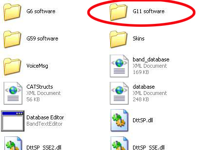
This folder contains
- firmware BIN file
- application called G11 FlashProgrammer.

Start FlashProgrammer.
1 .Check the connection status (it should say Connected!).
2. Click ERASE Firmware, then
3. Click WRITE Firmware.

If the loading is successful, the Firmware version and News Firmware version should both be v.0.1.4.
You can now write your G11 serial number. Any number would do at this stage.

Close and exit FlashProgrammer.
Firmware load is now completed.

Frimware check
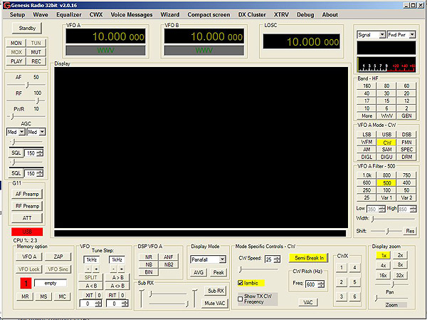
Start GSDR, go to "About" tab.If loaded correctly, the "About" window should look like this:

With GSDR software installed on your PC and firmware loaded to G11 board, you can now proceed with assembly.
Next phase: local oscillator.


