
Tuesday, February 16, 2016
5W0RR : a new one on QRP [worked with G11]
5W0RR Frm Samoa is fairly regular on 20m on JT65 mode. Saw him tonight - fairly weak- until I've realized that my antenna is pointing in opposite direction.
Called him again, while flicking the 180 degree SetppIR switch (yes you can do that while running QRP :-) and WOW he was booming in.
Easy exchange, and a new DXCC logged. Love my QRP DXing and love my DIY G11.
Nothing beats working a rare one with home-made radio!


Monday, February 15, 2016
G40 build notes
GenesisRadio G4 is a 40m single band SDR transceiver. Easy to assemble: all through-hole components!
It's been few years since I've assembled one so this is bit of a nostalgia project.
My G40 has been on WSPR for past few days generating almost 2000 decodes from 160 unique stations,
mainly form US and Europe.
If you happen to have G40 PCB then you may find this useful:
Band pass filters
AF amp jumpers
COM port settings
How to connect +V for RX


GenesisRadio G11 vs. EuropeanZZ
I can't resist but to share this one with you:
yesterday,  late afternoon, 20m band - and dozens and dozens of European stations on RTTY
coming via the long path. The antenna is pointed over Pacific,
practically no noise. Some signals are strong, other weak but perfect decode.
With SDR there is no tuning- it is just a matter of clicking on the signal
as it appears, and you call before anyone else. Also if you wish to call
you see exactly where to park your signal on a crowded band. Almost too easy!
late afternoon, 20m band - and dozens and dozens of European stations on RTTY
coming via the long path. The antenna is pointed over Pacific,
practically no noise. Some signals are strong, other weak but perfect decode.
With SDR there is no tuning- it is just a matter of clicking on the signal
as it appears, and you call before anyone else. Also if you wish to call
you see exactly where to park your signal on a crowded band. Almost too easy!
late afternoon, 20m band - and dozens and dozens of European stations on RTTY
coming via the long path. The antenna is pointed over Pacific,
practically no noise. Some signals are strong, other weak but perfect decode.
With SDR there is no tuning- it is just a matter of clicking on the signal
as it appears, and you call before anyone else. Also if you wish to call
you see exactly where to park your signal on a crowded band. Almost too easy!
Sunday, January 17, 2016
How many G11 DIY are on the air?
My G11 is the third assembled "do-it-yourself" transceiver. Here is the list of builders who successfully completed the project: 


[Builder's callsign, date and first-QSO call]
G11 #1 K9GQ 20 AUG 2015 KB0PPQ
G11 #2 VK2AMS 20 SEPT 2015 VK4WI
G11 #3 VK2DX 31 DEC 2015 CT1FBK
G11 #4 KF5KOG 5 JAN 2015 KD7H
G11 #5 AB4GS 24 JAN 2015 KB0PPQ
My first contact with G11 #3 was on JT65 mode with CT1FBK from Portugal. Easy!
In the GBOX
Couple of images of the finished unit, inside GBOX. This very robust enclosure comes from another project, will talk about it in detail later on.
You can find more about GBOX here.


GBOX is an aluminium die-casting enclosure with dimensions 240 x 240 x 90mm. There is plenty of room to accommodate a 100W amplifier as well.

G11 DIY: up and running!
A few months have passed quickly- and my G11 DIY is now completed. I intend to build one more unit and upload more images taken during the assembly process.
Stay tuned! The blue board is multiband filter board which is available from Bruce, KF1Z (see my first blog entry for details).


Sunday, August 2, 2015
Installation of GSDR software and FIRMWARE upload
If you haven't installed the GSDR software then now is the time to install it.


It is a good idea to start with a 'fresh installation'.
Create a folder GSDR C:\GSDR
The software consists of two files:Installation file and Latest update
Download Installation .zip, save it in C:\GSDR and unzip it. Then download update .zip in same directory. Unzip it, and overwrite any files when asked.

You should see the following files:

Click on Genesis.exe to launch the application.
Installation process will start with fftw 'wisdom'. Allow it to run.




FIRMWARE UPLOAD
1. The very first step is to disconnect and unplug G11 board.
2. Make a "PLUG". Simply solder ground, tip and ring of a 3.5mm stereo jack.
(You can also use for the low-impedance headphones for the same purpose).
PREPARATION phase
In preparation phase you need to get the G11 micro-controller into BOOT mode. Please follow the steps in exact order.
1. connect the USB cable
2. insert the "PLUG" into J2U Paddle connector
3. power up G11 board.
4. after 10 seconds, pull out the "PLUG".
G11 board is now in BOOT mode.
NOTE: DO NOT disconnect power or USB cable. Proceed on while leaving the G11 board powered-up and USB cable connected.
Firmware load
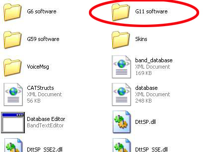
Go to C:\GSDR then into G11 software folder.
This folder contains
- firmware BIN file
- application called G11 FlashProgrammer.
Start FlashProgrammer.
1 .Check the connection status (it should say Connected!).
2. Click ERASE Firmware, then
3. Click WRITE Firmware.
If the loading is successful, the Firmware version and News Firmware version should both be v.0.1.4.
You can now write your G11 serial number. Any number would do at this stage.
Close and exit FlashProgrammer.
Firmware load is now completed.
Frimware check
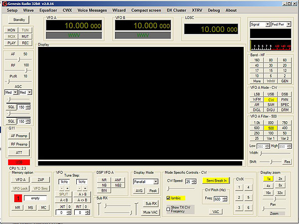
Start GSDR, go to "About" tab.If loaded correctly, the "About" window should look like this:
With GSDR software installed on your PC and firmware loaded to G11 board, you can now proceed with assembly.
Next phase: local oscillator.
Saturday, August 1, 2015
Micro-controller and USB assembly
The next assembly phase is completion of uC and USB connection unit. 


In addition to components shown on the page 12 of the schematic diagram, install DC connector J1P, C28P, C27P, on-off switch SW1, and two ferrite beads FB3P and FB4P. Those components are located at the top right corner of G11 PCB.
Also, install R11U, L1U, L2U and FB1U thorough-hole components. Don't forget to install all 4 LED diodes which are located at the bottom left part of PCB: LD1U, LD1S, LD2U, and LD3U.
Your G11 is now ready for first power-up. Apply 13.5V DC and check voltage on the U3U [5V]
Here is the photo of completed assembly:
Next step: connecting the G11 to GSDR and firmware update.
Subscribe to:
Posts (Atom)